Why Plastic Flows Better in Aluminum Injection Molds
by David Bank, Aluminum Injection Mold Co., Dave Klafhen, Advent Tool, Ron Smierciak, Alcoa Forged and Cast Products
The following article is an investigative study directly comparing melt flow characteristics of general purpose resins in QC-10 aluminum molds and P20 steel molds.
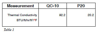
Table 1
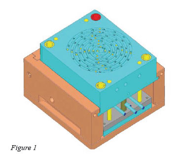
Figure 1
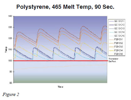
Figure 2
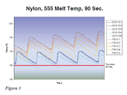
Figure 3
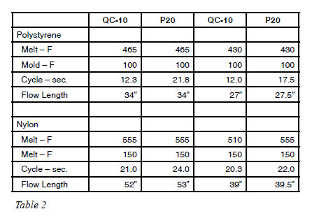
Table 2
There have been numerous articles published regarding the cycle time advantage aluminum molds have over steel when configured with the same gate, part geometry and cooling channels, but there is little specific information available to demonstrate why this happens and how it improves the injection mold process. Alcoa Forged and Cast Products (Newburgh Heights, OH) teamed up with Aluminum Injection Mold Co. (Rochester, NY) and sponsored a case study to uncover the differences known to exist when molding thermoplastics in aluminum versus steel molds.
The key objectives were to quantify the differences by comparing how thermoplastics react in an aluminum mold versus a steel one, measure those differences and share the results of the experiment. The results should help moldmakers and molders better understand the potential savings and improvements for molding plastic components in aluminum tools, specifically addressing the following:
1. How plastic material flows longer distances with less injection pressure, when compared to steel
2. How molds fill faster and more efficiently
3. How parts have minimal warp and better dimensional stability
Aluminums thermal conductivity is nearly five times greater than that of steel (Table 1). In an article published in Moldmaking Technology magazine1, Douglas Bryce discusses an IBM tooling study comparing identical aluminum and steel molds producing the same plastic components over a five-year period. The article suggested that the aluminum molds cost up to 50 percent less to build and can be delivered in one-half the time. It went on to say these tools produced higher quality products having cycle times that were 25 to 40 percent less than the steel molds.
In 2005, an article written in the publication Flowfront2 looked at computer simulation of cycle time and cooling versus actual molding. After carrying out simulations on 12 parts, which had very different characteristics in terms of shape, size and plastic materials, it was concluded that significant savings in total cycle time could be realized by using aluminum instead of steel molds. Cycle time savings of 10-20 percent were seen in cases where there were no critical tolerances linked to the deformation of the part due to the effect of the heat. However, savings of 60- 200 percent were seen in cases where heat deformation affected critical design tolerance levels.
Studies like these are relevant to the industry and this case study looks at the basis of why plastic flows better in aluminum.
Tooling
Spiral test molds, built in accordance to ASTM D3123-98 were selected for the tool design. This shape would standardize the channel length, size of overall mold, cooling and gate location. In addition, each mold was fitted with a series of four thermocouples to monitor and document, in real time, what the metal does when injected with molten plastic. All the thermocouples were connected to a data logger and computer for data collection. For the aluminum molds, a QC-10 mold plate was used and for the steel molds, a P20. Six molds of identical geometry were built - three in QC-10 and three in P20. The spiral mold shape was sized at 6mm wide and channel depths of 1mm, 2mm and 3mm, respectively. The sizes of the tools were a standard 7x8" master unit die and all the mold plates were the same thicknesses. The sprue diameter was identically sized for each of the six unit molds. Identical water lines were drilled to complete the cooling circuits. Four of the six molds, the 1mm and 2mm molds in both materials, were fitted with thermocouples that came in from the back and were approximately 0.5mm from the cavity surface. On the 3mm spiral unit molds, a fifth thermocouple was placed into secondary vent area to monitor the vent temperature during molding. All six molds were laser engraved on the "A" side in inch increments from 1" to 67". The surfaces were finished with a 600 grit stone. The test was set up in a 55 ton Toyo injection mold machine.
Seven unfilled, general purpose thermoplastic resins were selected for this trial: polyethylene, polypropylene, polystyrene, ABS, PC/ABS, nylon and polycarbonate.
Molding trials
Trial One: Same melt temperature, same mold temperature per manufacturers recommended parameters; seven resins, six tools
This trial fixed a predefined orifice, a predefined temperature and a predefined injection pressure (< 1000 psi). A 25-piece sample was run for each mold group. The hypothesis suggests that the flow lengths would be dramatically different between the QC-10 and the P20 molds because of aluminums higher thermal conductivity. The material was dried for the prerequisite period of time and prepped for molding. The melt temperatures were set to the resin manufacturers recommended settings and the molds were brought up to the manufacturers recommended temperature as well. The P20 molds were run first in all the materials. The data found the average spiral flow length to be 10" to 15", consistent with the manufacturers specifications. The QC-10 molds were run in all the materials as well, expecting to produce a dramatic difference in flow length. It did not.
The flow length results were in the same range of the P20 molds. The findings were puzzling. In the end, all the materials yielded basically the same results in all the molds used, which was not the expected outcome.
With over 25 years experience in processing aluminum tools, this trial was expected to demonstrate what is known to be true. The group had to stop and rethink the situation. It was searching for something it knew was there, but did not know how to quantify it, yet. After much discussion, it was decided that the group needed to run the same materials in a trial that included pack and hold.
Trial Two: Seven resins; six molds with monitored temperatures, pack and hold
The second trial was initiated, again recording temperatures. The injection mold pressure remained at the baseline of the material used from trial one. This time the experiment was to process each unit mold as if molding a run of parts in production. Each mold trial began as a short shot (shorter length spiral, in this case) and proceeded to pack out the part to get the best achievable result. Cycle was established when the sucker pin pulled the sprue clean and the part was cool enough to eject. Cycle time and mold temperatures were documented for each tool running at least 25 parts at cycle.
In the QC-10 molds, the temperature graph during this process showed a near vertical increase in temperature from mold set point of about 10 to 12 degrees to an immediate drop back to set point before the mold opened. For a point of reference, the mold cycle for polystyrene was 12.2 seconds as the QC-10 group of molds was finished. All three thicknesses, although yielding shorter flow lengths going from 3mm thick to 1mm thick, were in the same 12.0 to 12.5 second range for total shot-to-shot cycle.
The P20 steel molds were run at the same temperatures as QC-10. The first observation was the change in how the mold temperatures reacted as the molten plastic was injected. The temperature did not spike up and down with the same intensity as it did in the QC-10 molds. In addition, the cool down time was much more gradual. Also, P20 typically overran the mold temperature set point by an average of about 20 degrees. The increase in the mold temperature due to the injection melt was an additional 15-20 degrees. With all this excess temperature, i.e., mold overshooting and temperature increases with very slow recovery, a difference of 20+ second cycle shot-to-shot in P20 versus the QC-10 cycle of about 12 seconds was noted. At this point, we believed we had finally found the reason that plastic molds better in QC-10, and we decided to continue another trial to verify our findings.
Trial Three: Two materials, one amorphous and one semi crystalline, 3mm unit molds of QC-10 and P20, pack and hold
It was decided to use only polystyrene (amorphous) and nylon (semi-crystalline) with the 3mm unit molds in QC-10 and P20 in this verification trial because virtually no differences in flow length between any particular mold family and between any materials in the previous trials were found. It was important to look at melt temperature versus flow length versus cycle time. The trial began with temperatures on the low side of the resin manufacturers recommended barrel temperature for the resin being used. Mold temperatures were set to the lowest recommended set temperature. The P20 mold ran in both materials and cycle times, mold temperatures and injection pressure was noted. Then the QC-10 mold ran in both materials, again noting cycle times, mold temperatures and injection pressures. After compiling data, all temperatures were moved to the highest barrel temperature and each mold was run with both materials, again collecting same data. In both temperature tests in trial three for polystyrene, QC-10 cycle time stayed consistent with findings of trial two, 12-13 seconds. In the lowest temperature test, P20s cycle time was in the 20- to 21-second range, similar to trial twos findings, but in the higher temperature test, it jumped nearly 25 percent.
Findings
The QC-10 molds heated five times faster than the P20 molds, when set up to run each trial. Across all the trials, the QC-10 mold temperature stayed consistently within 1-3 degrees of the mold temperature set point. During the inject phase, a temperature spike of 10-20 degrees with an abrupt return to set point was observed.
The P20 mold temperature stayed consistently 10-25 degrees above mold temperature set point. During the inject phase, additional increases of 15-30 degrees were observed before slowly trending downward. When using the QC-10 molds, an appreciable change was not seen in cycle time, part to part, even when the materials were run at the high end of the manufacturers recommended melt/mold temperatures. However, the P20 molds continued to get hotter and the cycle time became even longer.
In view of these findings, it is not surprising that there are some plastic consultants extolling the virtues of running plastic resin as much as 100 degrees below the manufacturers recommended settings when using P20 or other steel injection molds, even though doing so could void the manufacturers guarantees.
Conclusion
The results of this experiment were both a surprise and not a surprise.
It was not a surprise to prove what the group set out to prove, but the road that led it there was an unexpected one. It was pleasing to show that plastic parts molded in aluminum would minimize warp and enhance dimensional stability, allow molds to fill faster and more efficiently and allow plastic material to flow greater distances with less injection pressure when compared to steel. It was demonstrated that using aluminum gives the benefit of making molds less expensive to produce, shortening mold delivery time, producing higher quality molded plastic parts and enabling the realization of producing more plastic parts per day.
The surprise in the experiment was that the expected results were achieved in a different, unexpected way. It was surmised that the desired results would be achieved because aluminum molds would take on heat from the hot melt during the injection phase, enabling the plastic to fill the mold cavity more quickly with less pressure and less density change. Conversely, it was thought that the steel molds would take on less heat, thereby creating more "skinning", and restricting the flow front resulting in the need for higher injection pressure and causing density changes from the gate to the longest flow length.
What we actually found was that the QC-10 did not take on or hold as much heat as was previously thought, thus allowing the molten plastic to move in quickly and quench quickly, therefore there was not a density change due to excess injection pressure. It was discovered that the steel actually took on and held much more heat. During the inject phase, plastic filled the cavity and stayed molten much longer, allowing for additional inject pressure, which caused density changes before solidification.
Hopefully the information provided in this article adds to the knowledge base used to consider aluminum as a viable choice for the production of injection molds.
References:
1. Douglas Bryce, Moldmaking Technology, "Why Offer Aluminum Molds for Production", April 2002
2. Claudia Zironi, Flowfront Magazine, "Competitive Advantages of Aluminum Molds for Injection Molding Applications: Process Simulation Used to Evaluate Cycle Times", April 2005
3. American Society for Testing and Materials (ASTM), West Conshohocken, PA. Is a nationally recognized independent test agency. The ASTM test number D3123-98 describes a spiral flow mold for use with thermosetting molding compound, and also states there appears to be no universal standard for thermoplastics.
For further information, contact Aluminum Injection Mold Co. at [email protected]; Dave Klafhen, Advent Tool, at [email protected] and Ron Smierciak, Alcoa Forged and Cast Products, at [email protected].